Thermocompressors have been successfully applied to dryer drainage systems. With the increase in machine speeds, and consequent drainage problems, the use of thermocompressors has increased. Knowledge of drainage system flow characteristics, thermocompressor performance, and control system to be used is necessary for proper application. The performance of thermocompressors under drainage system conditions is discussed and performance data given.
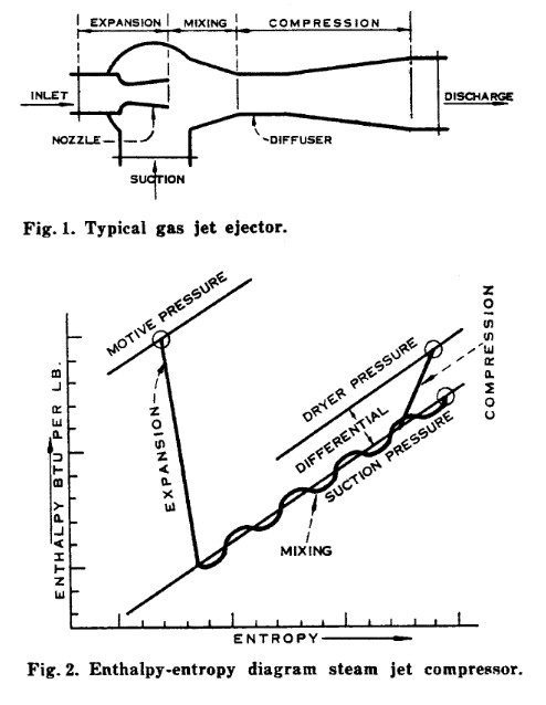
An ejector is a jet device which utilizes a fluid at high pressure to entrain a fluid at low pressure and discharge the mixed streams against an intermediate pressure. A steam jet handling steam is known as a thermocompressor, whether operating in the sub-atmospheric or in the pressure range. When operating in a vacuum, this type of unit is also often called a booster, or steam jet booster.
A thermocompressor is comprised of a motive steam nozzle, a mixing chamber, and a diffuser; see Fig. 1. The nozzle expands the motive steam from inlet to suction pressure and converts the pressure energy to velocity energy. In the mixing chamber, the jet of motive steam mixes with the suction stream. This accelerates the suction steam and decelerates the motive steam, producing a mixed stream at an intermediate velocity. At this point, the process of compressing the steam to discharge pressure begins. The diffuser is designed to reconvert the velocity energy into pressure.
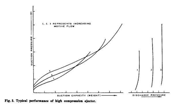
The enthalpy-entropy path is shown in Fig. 2. The nozzle expansion from motive to suction pressure approaches ientropic, but various friction and thermal losses exist. The amount of energy available for compressing the mixed stream is the change in enthalpy of the motive steam form motive to suction pressure. The energy available for compressing the suction stream is reduced by the energy required to recompress the motive steam. Mixing of the two streams is shown as a constant pressure process, although the actual process has never been completely defined. The compression approaches an isentropic condition, but is subject to various Iosses which are proportionately greater than the nozzle losses. The overall process is considered adiabatic since the thermal losses through the walls are insignificant. The outlet enthalpy is closely approximated by calculating a straight heat balance for the unit.
Thermocompressor performance can be divided into two types based on compression ratio (discharge pressure/ suction pressure).
When compression ratios exceed 2:1, the diffuser velocity exceeds the velocity of sound and the performance becomes critical. This type of ejector is essentially a constant flow device. For any set of motive, suction, and discharge pressures, the capacity is fixed. Figure 3 illustrates such performance.
The three curves show the effect of three motive steam rates. Physically, this is achieved by three different size steam nozzles with the same diffuser.
A similar set of performances can be obtained by a variable orifice nozzle. With a given constant motive steam flow, the suction pressure will vary with capacity provided the discharge pressure does not exceed the pressure shown on the discharge pressure curve. In Fig. 3, at any given motive rate, the suction capacity is constant and reproducible at any given suction pressure. The back pressure curve must be obtained by test. At a fixed suction capacity, the back pressure is raised until the suction pressure rises. This is known as the break point. The back pressure is then decreased until the suction pressure drops to the original point. This is known as pick-up and is the pressure plotted in Fig. 3. It should be noted that the capacity is unaffected by reducing the back pressure below the pick-up point. Also note that a decrease in motive flow increases capacity at higher pressures, provided the back pressure does not exceed the pick-up pressure. Any decrease in motive flow, or increase in discharge pressure, significantly beyond the design condition will cause a discontinuity in performance (break) and the unit will revert to approximately 2:1 compression. For this reason, most critical thermocompressors are supplied with fixed nozzles, and capacity is varied by turning on and off multiple units.
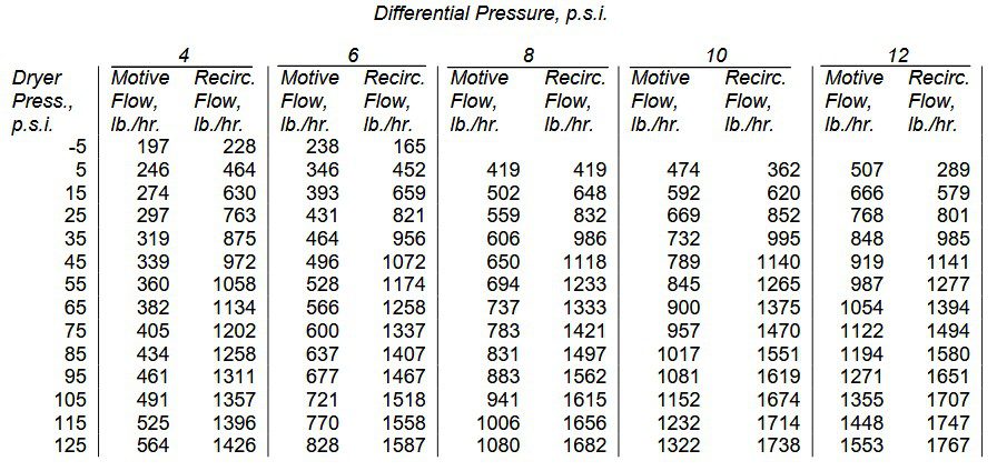
Units designed to operate with low compression ratios do not require super-sonic diffuser velocities and do not exhibit any discontinuities in performance. Dryer drainage systems utilize non-critical units. Figure 4 illustrates performance of such a unit showing variation in capacity with variation in motive flow.
Increased motive flow increases suction capacity at a given discharge pressure.
This type of thermocompressor is usually furnished with a variable orifice nozzle, either manually or power operated, as shown in Fig. 5.
The orifice opening is varied by a spindle. The tip must be specially shaped to maintain a proper jet stream from the nozzle. The stroke versus flow
approaches a linear function rather than proportional. This must be taken into account in designing the control system. The unit illustrated uses a “Fisher” air piston with positioner to operate the spindle. A fixed nozzle unit can be controlled by a motive steam valve, but this sacrifices some available energy at reduced flows. Figure 6 shows the losses in available energy when reducing 200-p.s.i. steam to 75 per cent and 50 per cent flow for various dryer pressures. When dryer pressures are high, it is obvious that the thermocompressor will not operate at reduced flows unless a variable orifice nozzle is used.
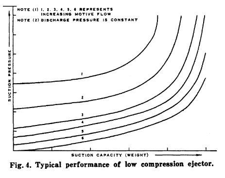

Figure 7 is a diagram of a simplified dryer drainage system without a thermocompressor.
There are many variations, but the basic connections and components are common to most systems. Steam, in addition to the amount condensed in heating the dryer, is blown through the system to remove condensate. A positive pressure differential across the syphon is required to properly evacuate condensate from the roll. The flow of blow-through steam assists in removing the condensated and non-condensables as they accumulate in the dryer. The large volume of blow-through, relative to the condensated volume, reduces the fluid density in the syphon and therefore the pressure drop, as well as maintaining velocity through the dryer and drainage piping. The required differential varies with the dimensions of the dryer and syphon, syphon design as well as the condensing rate and machine speed. Dryer drainage systems without thermocompressors rely on blow-through to lower pressure dryer banks in a cascade system, air heater, other mill processes, or condenser.

Figure 8 shows the same system modified for thermocompressor operation. The use of a thermocompressor to promote circulation eliminates the need for cascading, permitting increased flexibility and reduction in the total steam used by reducing blow-through to condenser. The first thermocompressor application was on Yankee dryer machines to recirculate the large quantities of blow-through steam. Utilization of blow-through of 7000 to 8000 lb. / hr. is difficult in many installations.
In recent years, it has found advantages to apply recirculation by thermocompressors to newsprint and kraft machines with dryer sections or banks. As machine speeds increase, the differential required to remove condensate increases and cascade systems require too low a condenser pressure to meet differential requirements causes over-drying (case hardening).

The proper combination of dryer system and thermocompressor requires knowledge of the behavior of both the systems in question and thermocompressor performance under various operation conditions. The pressure drop function of a dryer drainage system is rather complicated. The steam supply system from the control valve (or thermocompressor) into the dryer inlet behaves in accordance with normal pressure drop functions for gaseous flow. The pressure drop will therefore be a function of pressure, temperature, and weight of steam flowing. The weight of steam, however, is made up of the amount required to heat the dryer, plus the blow-through quantity. The pressure drop function through the syphon to the separating tank (flash tank) is more complicated, since the flow is two- phase. The pressure drop will be a function of pressure, temperature, weight of condensate flowing, and weight of blow-through. On dryers with rotating syphons, the dryer diameter and surface speed add another variable. With thermocompressor systems, the pressure drop from the separator to the thermocompressor is a gaseous flow function of pressure, temperature, and weight rate of blow-through.
The thermocompressor must compress the blow-through steam across the total pressure differential consisting of the sum of the three pressure drop functions. Practice has been to determine the required pressure differential empirically for good drying on the given machine. There also seems to be a
tendency, in the mill, to assume that once determined this pressure differential is a constant for all dryer pressures and machine speeds where rimming occurs, rather than determining the actual safe differential over the desired operating range.
It is not the purpose of this paper to discuss design of dryers or dryer drainage systems. However, proper application of thermocompressors to such systems requires a knowledge of the behavior of the dryers and drainage system, thermocompressor behavior, as well as method of control. The performance of a non-critical thermocompressor has no discontinuities and will therefore seek an equilibrium point in a closed loop such as a dryer drainage system. The differential can be controlled by the thermocompressor spindle position. This will occur if the thermocompressor is designed to have a performance curve with a slope opposite to that of the differential curve. The thermocompressor manufacturer should be advised as to the type of control system so that proper design criteria can be set up.
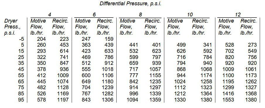
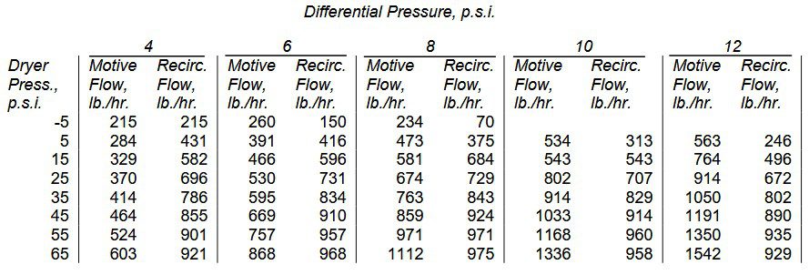
The performance of a thermocompressor was determined under varying operating conditions. For purposes of simplicity, a constant motive steam pressure of 200 p.s.i. D&S was used for all the curves in Fig. 9 and 10. Detailed data are given in Tables I, II, III, and IV. The performance is similar at higher or lower motive pressures, but the pattern changes depending upon the dryer pressure range. Dryer system differential is a parameter and performance and capacities are shown for 4, 6, 8, 10 and 12 p.s.i.
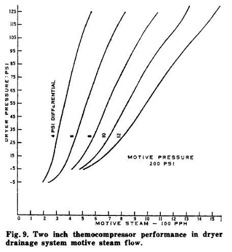
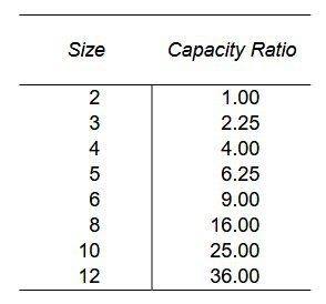
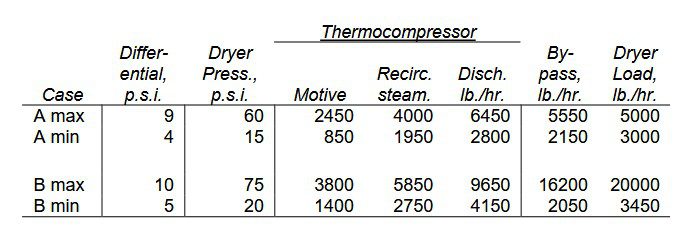
To use the data, the known differential requirements of the system are spotted for maximum and minimum conditions. For example: For Case “A”, consider a dryer section. Maximum condition 9 p.s.i. differential with condensing load of 8000 lb./hr. at a dryer pressure of 60 p.s.i. From Fig. 9, interpolating between 8 and 10 p.s.i. differential, the motive steam is 790 lb./hr. for a 2-in unit. The required condensing load is 8000/790 = 10.1 times 2-in. capacity. Table IV shows an 8-in. size is required. From Fig. 10, the unit would be capable of 1290 x 10.1 =12,100 lb./hr. recirculated steam (blow-through). A
normal dryer section pressure differential function would require much less blow-through for 9 p.s.i. differential. Assuming the given dryer section requires about 50 percent blow-through, the thermocompressor should be
designed for 4000 lb./hr. suction flow which would require 4000 (790/1290) =2450 lb./hr. motive. The size factor would be 4000/1290 = 3.1, requiring a 4-in. thermocompressor. The minimum condition was a condensing load of 3000 lb./hr. at a dryer pressure of 15 p.s.i. and a differential of 4 p.s.i. The thermocompressor will use 3.1 x 275 = 850 lb./hr. motive steam and recirculate 3.1 x 630 = 1950 lb./hr. If the differential pressure requirement of the dryer drainage system approximates these flows, the thermocompressor will be satisfactory. If the blow-through requirement at either point is higher, the thermocompressor should be designed to meet the maximum point. The spindle control will then permit operation at the desired back pressure.
Case “B” is another sample set of conditions which are summarized in Table V with thermocompressor data taken from Fig. 9 and 10 for a 4-in. thermocompressor.

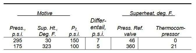
There is a secondary benefit from the use of a thermocompressor related to the amount of superheat in the steam to the dryer. This is particularly pertinent to Yankee dryers where the thermocompressor supplies most of the steam. The recirculated steam from the flash tank is wet. A quality of 97 per cent is about as dry as can be expected. The mixing of this steam with the thermocompressor motive steam reduces the superheat to levels which do not affect the dryer operation. Table VI shows two actual examples.
The first case is not severe since the amount of superheat is low. The second case with 360 Deg. F. superheat at the dryer would require desuperheating were it not for the effect of the thermocompressor.
The wide use of steam jet thermocompressors in dryer drainage systems is proof of its advantages. The performance characteristics of thermocompressors are suited to the differential characteristics of paper machine dryers. For small dryer pressure and load ranges, thermocompressors can control to a constant differential. For wide ranges, dryer operation with differential varying as a function of dryer pressure will provide the most satisfactory operation.
When accurate and complete data on dryer differential capacity and control system are available, thermocompressors can be designed which will function well in paper machine dryer drainage systems.