
In this process the pulp is obtained by digesting wood chips with an acid liquor at high pressure and temperature. This is a batch process starting with the filling of wood chips, charging with liquor, bringing up to pressure and temperature, cooking and discharging pulp to the blow tank. A “chip packer” is sometimes used to distribute the chips evenly without piling. The “packer” uses steam jets to spray the chips over the digester area.
1. A typical application of Schutte and Koerting Equipment is the use of a blower to augment draft from the digester during tank charging. The residual gases after the blow and the steam used by the “packer” is vented to stack. The rate of ship flow is increased by increasing the rate of venting by SK blower.
Tank volume 5100 cubic feet. Fill time 45 minutes. Use a #2 Figure 402, 4X Blower. Unit will handle 1050 cfm at 20 inch water draft, using 1600 pph steam at 125 psi.
In sample – vent line is 8” stainless steel ductwork – Figure 402 would be stainless steel flanged to mate ductwork.
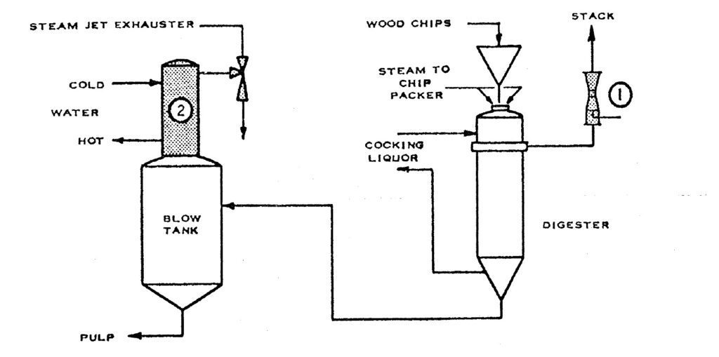
2. Direct contact counter-current heater for reclaiming heat in blow steam. With the bottom inlet design, unit is mounted directly on top of the blow tank. The unit is also non-closing with white water. A steam jet exhauster is used to pull a draft to prevent any blow-by of vapor into operating areas. With this heater and exhauster 100 F temperature rise with the outlet temperature at 200 R is obtainable. Note: These heaters are widely used on blow tanks from continuos digester systems.
REFERENCE:
#1 Bulletin 4AB
#2 Bulletin 5AA & 5E
In Sulphite Mills black liquor is concentrated through multi- stage evaporators before burning, the final stages are normally under vacuum.

REFERENCE:
#1 Bulletin 5AA
#2 Bulletin 4F
Digested pulp is washed to remove impurities and chemicals. This is carried out in several stages with recirculated water. The use of hot water at the last stage of washing facilitates washing and results in a dryer pulp coming off the washer. Washing also must be carried out after bleaching to remove chemicals.

REFERENCE:
Bulletin 3A
There are many uses in a paper mill for convenient quickly available hot water under pressure for washing down tanks and floors after spills, paper break or for general cleaning, the nature of paper pulp is such at this point that relatively hot water in a high velocity stream greatly expedites the work of dislodging and washing away the pulp.
A typical application is an S&K Figure 320 heater to supply hot water hoses on machine room floors.
Sample performance: 1-1/2” Fig. 320 continuous heater discharging 36 gpm of water at 120 F. Cold water supplied at 40 psi and 40 F, steam at 40 psi. Water is discharged through piping to outlets along the machine with high pressure hoses. Unit may be thermostatically controlled for temperature regulation and motorized valves may be used for push button starting.

REFERENCE:
Bulletin 3A
Large quantities of steam are used for heating of various liquids in the manufacture of paper. The heating of stick, in all its consistencies from white water up, is usually carried out by direct addition of steam. The greatest amounts of steam are required at time of start up to bring the stock system up to paper making temperatures. During paper manufacture amounts of steam are much less but vary upon water conditions. The direct addition of steam without some mixing devices causes excessive vibration and hammering which is sometimes destructive. The presence if fibres has, in the past, prevented the use of devices designed to eliminate the noise. The S&K line of Fig. 314 sparger nozzle is particularly adaptable to the heating and agitation of fibrous and granular solids in suspension of liquids.
1. Heating and agitation of white water in wire pit
3” Fig. 314’s are used for heating at start up with 1-1/2” units used during paper making to hold temperature.
Sample performance: Two banks of five 3” Fig. 314’s each to pass 40,000 to 50,000 pph of steam at 60 psi for start up heating to 115 F. One bank can be shut off for recduced steam requirements in milder weather. An additional bank of five 1-1/2” units would be utilized to maintain temperature during running time.
Sparger Nozzles used in wire pit sump to heat and agitate to prevent build-up summp 10 ft. wide, 4 ft. long, 2 ft. deep which requires six 2” Fig. 314’s passing 10,000 pph at 50 psi. Each unit will recirculate 260 gpm or a total of 1560 gpm. Since sump contains 3000 gals. This will give a two minute turnover. If heaters are connected with two steam lines, one for two heaters and one for four heaters, range of flow would be from 10,000 pph with 50 psi on all heaters down to 1500 pph with psi steam on two heaters.

REFERENCE:
Bulletin 3A
The wet felts are used to support water saturated web on the paper machine through the felt sections. Since the water is pressed out of the paper into the wet felts, it is necessary to remove this absorbed water from these felts continuously. It is also necessary to wash the wet felts periodically to remove fibres, starch, sizing, ect. Soaps or detergents are added to water to improve the washing process.

½ ig. 242 to handle ¼ gpm/ soap solution using 3 gpm of water at 40 psi. discharging against psi to feed spray nozzles.
REFERENCE:
Bulletin 2M Supplement
Special Figure 242 Eductor
After the web of paper is formed on the wet end of a paper machine it must be dried at a controlled rate, depending upon the type of paper. This is performed by one ot more steam heated dryers. Modrn tissue machines only use one large roll, called a Yankee dryer, whereas news print machines have 40 to 50 dryer rolls operatied in banks. These rolls rotate with peripheral speeds up to 2600 ft. per minute. The consequent rotational speed makes it difficult to prevent condensate build-up on the inside surface of the roll. In order to provide uniform removal of condensate is is neccessary to “blow through” excess steam which carries the condensate in suspension through the condensate removal system. In machines with several banks of dryers the dry end is operated at the highest pressure and the “blow through” from this section utilized to feed the next section. The pressures are therefore cascaded down to the first set of dryers on the wet end which may act as condensers, or is blown through from them into air heaters or some other use of low pressure steam. The wet end may be operated under vacuum depending on the dryer temperatures desired. On Yankee dryers blow trhough may be utilized in air heaters (for ventilating air above dryer rolls). Heating of water for felt washers or other steam users or, in some cases, simply blown to atmosphere. A thermocompressor may be used to entrain blow through steam and recirculate to inlet of dryer. All or part f the steam needed to heat the dryer is added through the thermocompressor nozzle. The energy obtained from reducing the pressure of this steam is utilized to entrian steam from the flash tank and return it through the dryer roll, working against the pressure drop necessary to sweep ou the condensate. Any additional steam required is added through make –up valve in parallel with thermocompressors.
REFERENCE:
Bulletin 4F

REFERENCE:
Bulletin 4F
Preparation of solutions of Lufax 295 for commercial use is facilitated by the use of an eductor equipped with a polyethylene hose attached to the suction inlet. This hose, which may be of any convenient length, can be inserted directly into the shipping drum, and thereby avoids handling of powder and potential dusting problems. The water floe through the eductor thoroughly wets and evenly distributes the resin in the dissolving tank. Agitation in a 500 to 600 gallon tank with a one to three horse-power mixer completely dissolves the resin at 4 to 6 percent solids in one or two hours.
It is important that the eductor hose be kept clean and dry at all times since the resin powder is very hygroscopic and moisture may cause blockage. The proper jet eductor would be an SK Fig. 220 syphon 1 ½” Bronze. A ¾” ID semi-rigid polyethylene hose can be used with this fitting. For a dissolving tank, 316 stainless steel is recommended. The simplified drawing labeled Fig. 1 shows equipment suitable for preparing solutions of Lufax 295.
